Why do I need a PFC in the switching power supply?
PFC stands for Power Factor Correction.
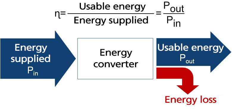
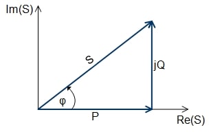
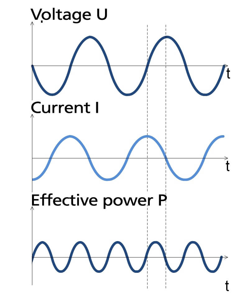
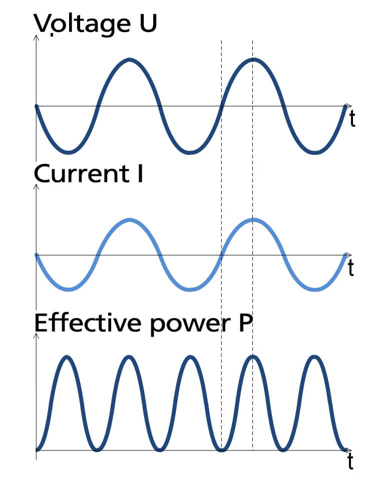
As previously described, a high power factor represents an effective use of electrical energy. Therefore a phase equality between current and voltage, as well as as ideal as possible sinusoidal curves is to be striven for in principle.
A simple phase shift between current and voltage due to linear impedances are rather rarely the case. In the case of a linear inductive load, for example, a simple capacitor can be connected in parallel to effect power factor correction.
Significantly more often, however, consumers are non-linear and no longer draw their current from the public power supply network in a sinusoidal manner as in the past, but in a pulse-shaped manner. Cause for this is the ever further spread of devices, which represent electronically regulated loads.
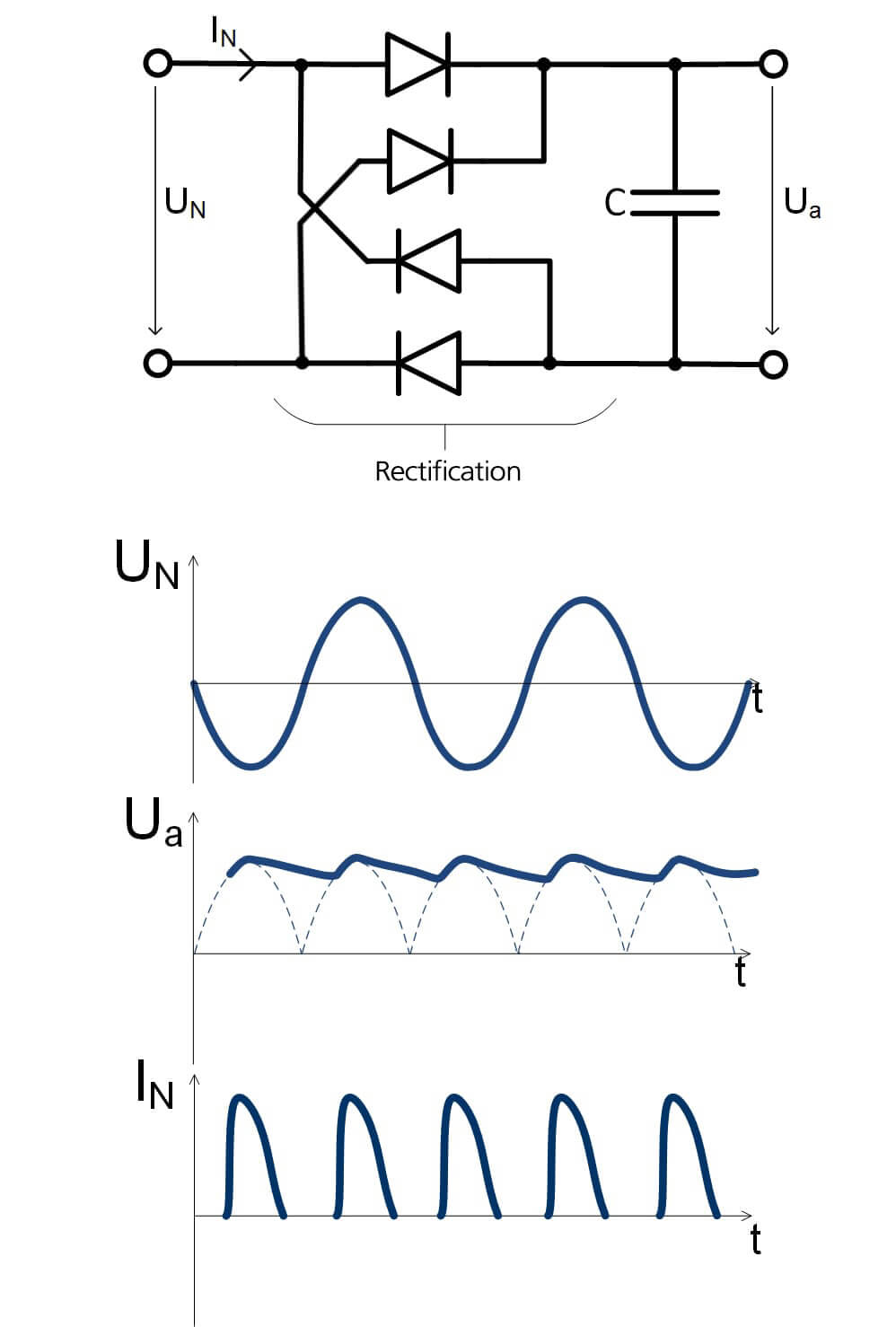
A switching power supply is such a typical nonlinear load. In its simplest form, the power converter consists of an input circuit with a half-wave or full-wave rectifier, followed by a storage capacitor to provide an unregulated DC voltage (intermediate circuit voltage). This topology draws current only when the line voltage is greater than the DC link voltage, i.e., only at the peaks of the line voltage, so that the filter capacitor is recharged in pulses via the rectifier diodes. Each pulse contains enough energy to supply the load until the next voltage peak (Fig. 4).
The resulting output current is highly distorted compared to the sinusoidal input and contains a number of harmonics.
The phase shift between current and voltage creates reactive power that utilities can only handle by oversizing all components in the utility grid. To prevent this, the EU first initiated the EN60555-2 standard ("Reactions in power supply systems caused by household appliances and by similar electrical equipment. Part 2: Harmonics") and, from 2001, the European standard EN61000-3-2 ("Electromagnetic compatibility (EMC); Part 3: Limits; Section 2: Limits for harmonic currents (equipment input current < 16A per conductor)"). This prescribes a limit on the level of harmonic currents from the mains for all equipment with a power consumption of more than 75W.
These specifications can only be met by correcting the power factor with a PFC.
The PFC extends the current draw from the grid, reducing the magnitude and speed of the rise of the current through the rectifier diodes, which reduces the number and magnitude of the harmonics.
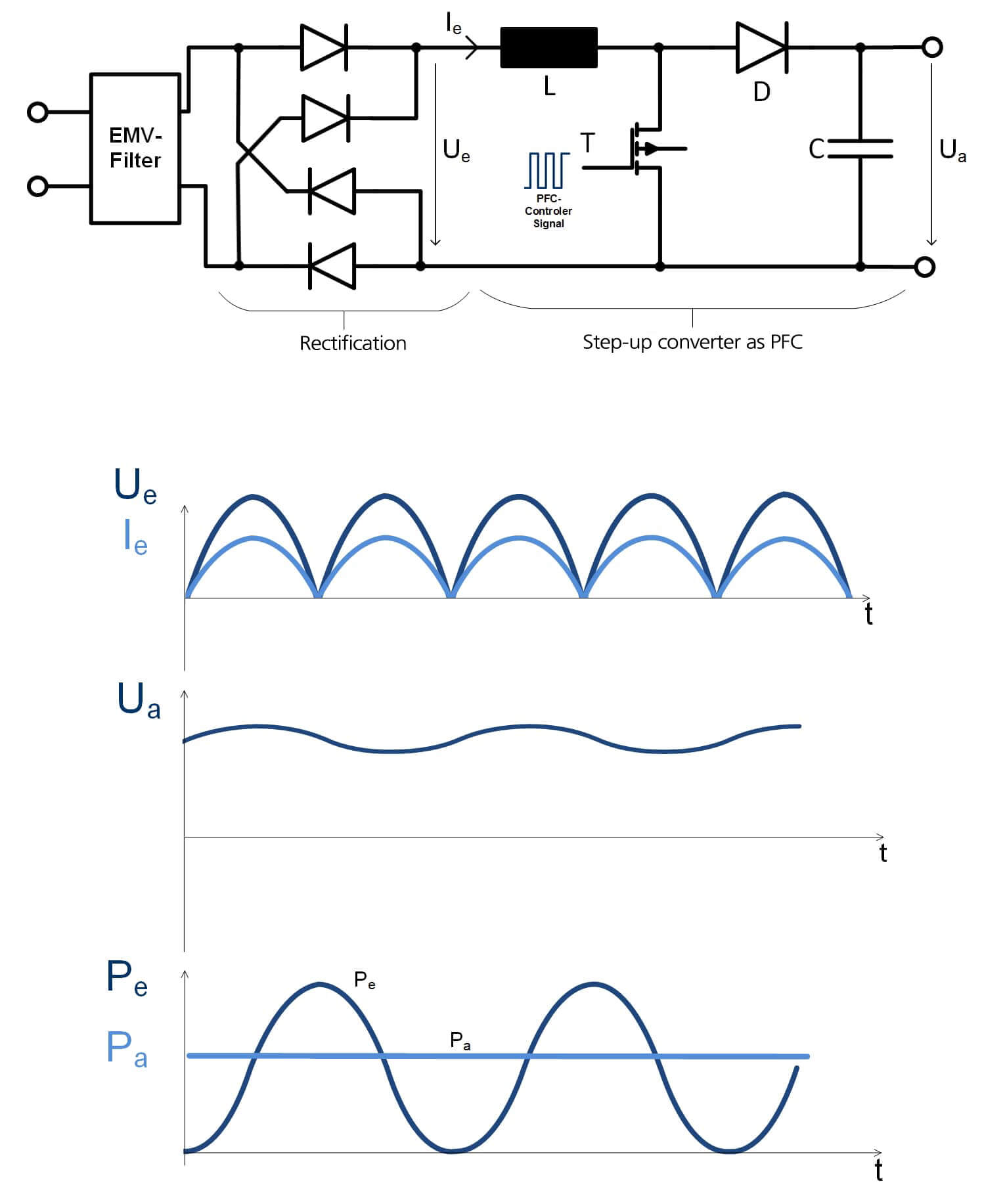
To achieve this, one uses a boost converter (see Fig. 5).
However, the PFC differs from the boost converter in the control.
While the output voltage is converted as usual to a higher than the highest possible input voltage (this is 360V in the European network),
however, the transistor is clocked so that the mains current is almost sinusoidal.
The current in the inductor is managed so that it is proportional to the input voltage Ue.
The regulation of PFC:
The regulation and control of the switching transistor is performed by various integrated circuits, PFC controllers.
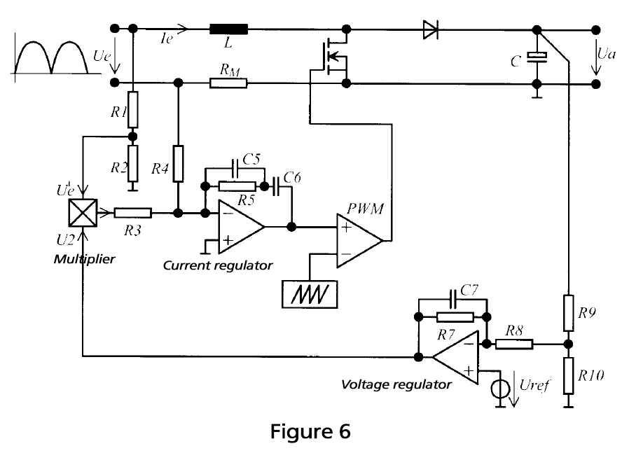
Basically, two control loops are needed:
A control loop that adjusts the input current of the PFC Ie proportional to the instantaneous value of the input voltage Ue. This is because only when this current follows the sinusoidal input voltage is the line current also sinusoidal and in phase with the line voltage. This control loop is called a current control loop.
A second control loop adjusts the rms value of the choke current so that the average output voltage Ua of the PFC remains constant despite varying output power. This control loop is called the voltage control loop.
So, in summary:
The rms value of the input current is controlled by the voltage control loop, whereas the current control loop ensures that the input current is sinusoidal.
The active PFC generates additional high-frequency interference, which must be suppressed with an upstream passive line filter.