


Cable Assembly
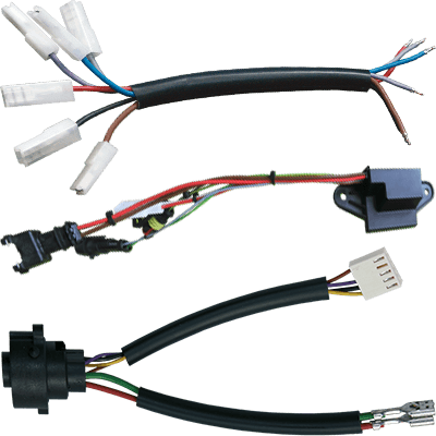
Standard and custom cable assembly tailored to your requirements. We develop and manufacture single wires, ribbon cables, FFC cables, HDMI cables, cable harnesses, mains leads and other interconnects for industrial, automotive, medical and equipment applications. Ideal for series projects with defined lengths, connectors, testing and documentation.
Single Conductors
exactly for your requirements
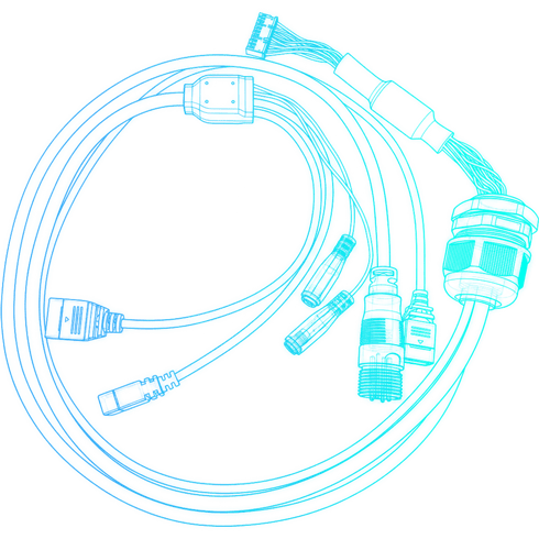
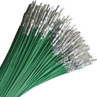
We offer individual cable assemblies with single conductors, precisely tailored to your specific requirements.
Our solutions are used in a wide range of applications, including mechanical and plant engineering, electronics manufacturing, industrial automation, the automotive sector and control cabinet construction.
In addition, we realize customer-specific designs for numerous further industrial fields of application. In doing so, we take both electrical and mechanical requirements into account and reliably implement them in high-quality, practical cable assemblies.
| cut | 0.05 mm² – 25 mm² |
|---|---|
| crimped | 0.05 mm² – 16 mm² |
FFC Cables
standard and customer-specific
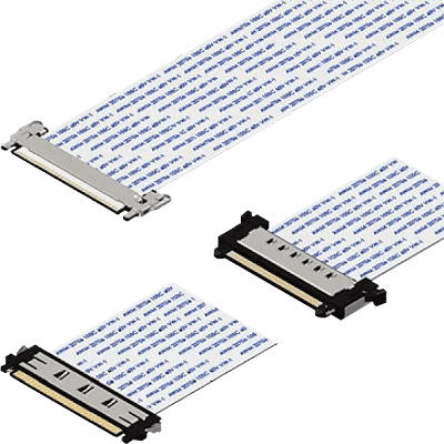
We offer the cable assembly of FFC cables with SMD FFC connectors, precisely tailored to your requirements.
FFC cables are characterized by their low weight, low profile height and high flexibility, and are easy to assemble with SMD FFC connectors. The insulation material of the FFC cables is made of PET.
A wide variety of FFC versions can be realized. In addition to our standard FFC cables, we can individually adapt parameters such as transmission frequency, die-cutting, current carrying capacity, shielding, bending radii and temperature resistance.
| pitch | 0.5 mm, 0.8 mm, 1.0 mm, 1.25 mm, 2.54 mm |
|---|---|
| variants | gold-plated contacts, folded, shielded, with/without shield bonding, die-cut, … |
| special parameters | transmission frequency, die-cutting, current carrying capacity, shielding, bending radii, temperature resistance, … |
Ribbon Cables
space-saving connections
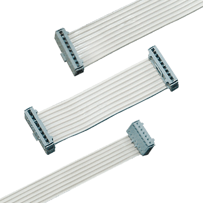
Ribbon cables and jumpers are predominantly used in the automotive industry in air conditioning units and in vehicle doors.
We cut all common pitches to the required length and subsequently terminate them with PCB connectors, e.g. Micro-Match or header connectors.
HDMI Cables
customer-specific and standard
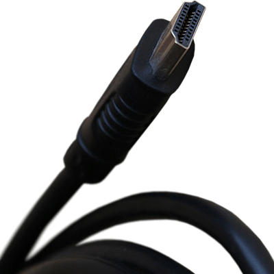
Our HDMI cables reliably transmit high-resolution audio and video signals between devices. They are available in various lengths and designs and support the latest HDMI standards, including 4K, 8K and HDR, as well as HDCP-compliant content.
The cables are characterized by high signal quality, stable plug connections and durable materials. Thanks to high-quality shielding, they are insensitive to interference and ensure trouble-free transmission even over longer distances.
Hotmelt
classic connection techniques vs. component sealing
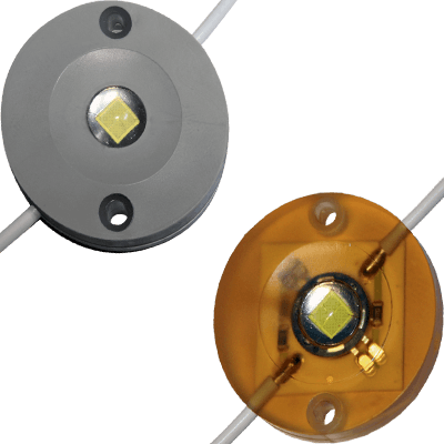
We offer you the possibility to seal electrical and electronic components using hotmelt, thus protecting them against unwanted or improper access. With the hotmelt process, grommets can be moulded precisely where they are needed. The potting compound can additionally contribute to strain relief. Eliminating conventional potting housings, energy-intensive heat curing processes and aluminium moulds leads to a significant reduction in overall costs.
Power Cords
VDE certified for industry and medical applications
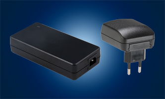
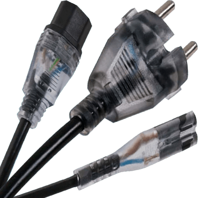
Assembled power supply cables (power cords) VDE certified for industrial and medical applications with a wide range of approvals from domestic and international testing bodies.
Available range: Euro plug, Schuko plug IP44, contour plug IP44, UK plug, Swiss plug, Italian plug, Australian plug, South African plug, Chinese plug, Japanese plug, North American plug, Hospital-Grade, appliance inlet C14, appliance coupler C13 / C17, small appliance coupler C7 / C5, central appliance coupler C19, extension cables, kink protection grommets, power cords with switch, cable cut to length by the meter.
Automotive
for maximum reliability and efficiency
For the automotive sector, we offer specially assembled cable sets that meet the highest requirements for reliability, flexibility and protection. They connect control units, sensors and actuators efficiently and in a space-saving manner, and are vibration-proof, temperature-resistant and resilient against moisture, oil and other vehicle fluids.
Clear bundling and labelling of the conductors simplifies assembly and reduces errors, while individual adjustments to length, shielding or connector types enable a precisely fitting solution for every application.
Wire Harnesses
for automotive, commercial vehicles and industrial electronics
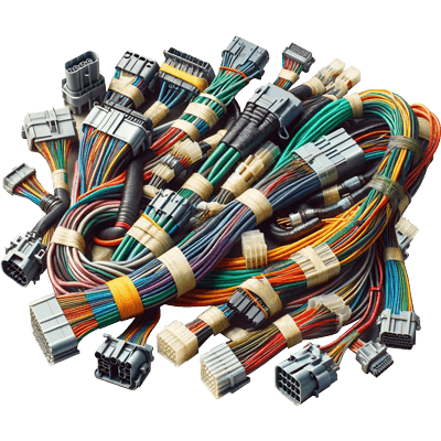
Sophisticated wire harnesses with or without overmolding according to your specifications for the automotive, commercial vehicle and industrial electronics sectors.
Comprehensive consultation and close project support are a matter of course for us – not only for high-quality cable assemblies in standard designs, but also for customer-specific wire harnesses tailored precisely to your requirements.
For custom designs, we offer a wide material selection for the outer jacket as well as protective and shielding braids with heat-resistant, water- and chemical-resistant sheathing.
The production standard for wire harnesses is certified to DIN EN ISO 9001:2008, ISO TS 16949 & UL.
Brochures
Here you will find bundled information on the topic as well as selected brochures with further content, technical background information, and practical solutions.

Frequently asked questions about
Cable Assembly
The questions on this page come from conversations with engineers designing a component in and with buyers who need to replace an existing type. They range from the basics to the details that show what really matters during selection. Whatever remains open we clarify for your specific case: tell us your target values – we narrow down the eligible series and give you price, availability and samples for your quantity.
01
What is the difference between a cable, a cable assembly and a wire harness?
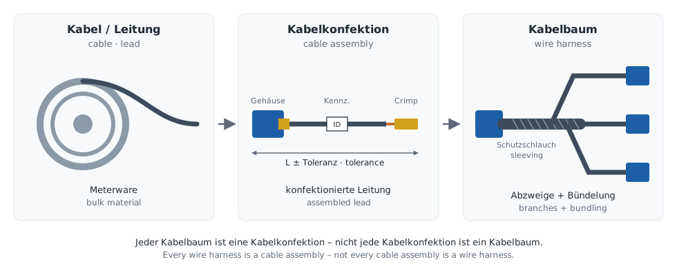
The difference lies in the degree of processing: a cable is bulk material, a cable assembly turns it into a ready-to-fit connection with a defined length, termination and marking, and a wire harness combines several such connections into one branched assembly.
- Cable or lead: semi-finished material off the drum, described by conductor stranding, cross-section, insulation and sheath. Strictly speaking, German electrical engineering distinguishes between cables (Kabel), which may be laid in soil or water, and leads (Leitungen) for equipment and installation – what gets assembled is almost always a lead, even though “cable assembly” has become the established term.
- Cable assembly (also cable assembling): cutting to length, stripping, terminating the contacts by crimping, soldering or insulation displacement, loading the connector housings, marking and testing. The result is an assembled lead built to drawing.
- Wire harness: several assembled leads with defined branches, bundled and protected by tape, sleeving, braid or overmoulding. Every wire harness is a cable assembly, but not every cable assembly is a wire harness.
The consequence for the design engineer: a cable assembly is not specified by its cable but by its connection. Length with tolerance, contact system, pin assignment and test scope belong in the drawing – the cable type is just one line of it.
02
Which conductor cross-sections can be crimped, and which can only be cut?
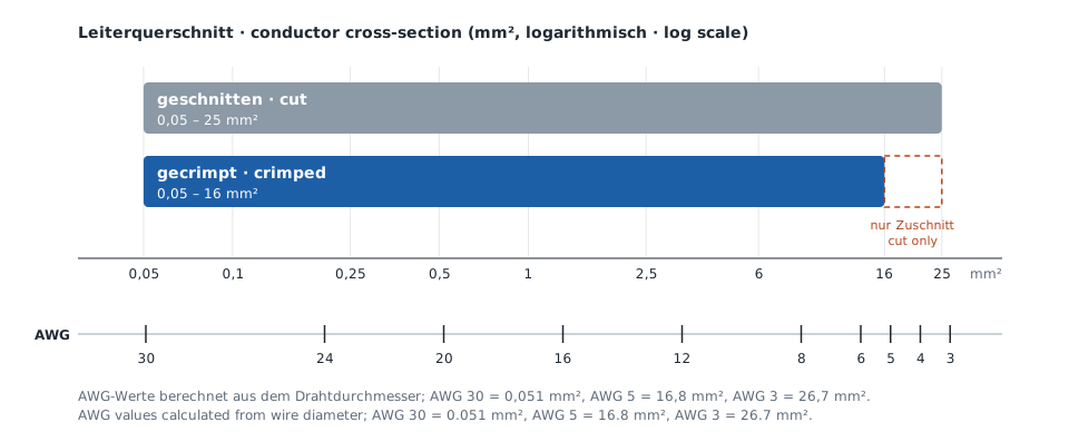
Single wires are crimped from 0.05 mm² to 16 mm² and cut from 0.05 mm² to 25 mm². Between 16 and 25 mm² the lead is therefore available cut to length, but crimping does not cover this range.
Anyone designing in AWG should note that the AWG and mm² series do not coincide. The limits correspond roughly to:
- 0.05 mm²: AWG 30 (0.051 mm²), the lower limit for fine signal and sensor leads
- 16 mm²: between AWG 6 (13.3 mm²) and AWG 5 (16.8 mm²)
- 25 mm²: between AWG 4 (21.2 mm²) and AWG 3 (26.7 mm²)
A crimp contact is not designed for a single cross-section but for a cross-section range, a conductor stranding and an insulation diameter. A flexible class 5 conductor and an extra-flexible class 6 conductor to IEC 60228 may therefore require different contacts or crimp tools at the same cross-section. Whether the joint is right is shown by crimp height, pull-out force and cross-section analysis; requirements and test methods are set out in EN 60352-2.
How leads above 16 mm² are to be terminated, for example with a tubular cable lug or via a screw terminal, is something we clarify with you in the project.
03
Why does an FFC with the right pitch not automatically fit every FFC connector?
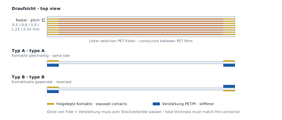
Besides the pitch, an FFC connector also defines the contact side, the thickness in the mating area and the contact finish – if one of these values is wrong, the FFC cable can often still be inserted but makes unreliable contact or none at all.
- Pitch: 0.5 mm, 0.8 mm, 1.0 mm, 1.25 mm or 2.54 mm – the starting point, but only one of several values.
- Contact side: exposed on the same side at both ends (type A) or reversed at one end (type B). This decides whether the connectors on both boards can face the same direction.
- Stiffener: a reinforcement of PET or polyimide in the mating area, whose thickness has to match the clamping height of the connector.
- Contact finish: tin-plated or gold-plated, matched to the connector contact. Mating gold against tin is considered unfavourable because it promotes fretting corrosion.
- Shield: a shielding foil is only effective when it is bonded. Shielded FFC cables are therefore available with and without shield bonding to a conductor.
What counts is the datasheet of the respective FFC/FPC connector, not the designation of the cable. Die-cut contours, folds, bending radii, current-carrying capacity, transmission frequency and temperature resistance can also be adapted to the installation space; the insulation material is PET.
04
When is a ribbon cable the better choice than an FFC?
A ribbon cable is the better choice when the connection has to be robust and quick to terminate and standard connectors are sufficient; the FFC cable wins where height, weight and fine pitches matter.
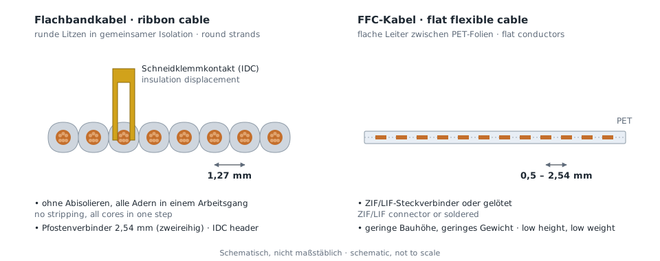
The difference lies in the construction: a ribbon cable consists of round stranded conductors in a common insulation, an FFC of flat conductors laminated between two PET films. This leads to the selection criteria:
- Termination: ribbon cables are terminated by insulation displacement (IDC) – the contact cuts through the insulation, and all conductors are connected in one step without stripping. FFC cables are inserted into ZIF or LIF connectors or soldered on
Example: Micro-MaTch (TE Connectivity), IDC box headers - Pitch: ribbon cables are usually at 1.27 mm conductor spacing, and IDC headers on a 2.54 mm grid take them in two rows. FFC cables go down to 0.5 mm.
- Retention in the connector: IDC connectors with latch and strain relief secure the cable mechanically; a ZIF connector holds the FFC only by the clamping force of its actuator.
- Height and weight: here the FFC is ahead, because it is barely thicker than its films.
That is why ribbon cables and jumpers are preferred where vibration and paced assembly matter, for example on air-conditioning units and in vehicle doors – and FFC cables where space between two boards is tight.
05
What is the difference between hotmelt moulding and overmoulding in cable assembly?
Hotmelt and overmoulding differ above all in pressure and material: in the hotmelt process a hot-melt adhesive, usually polyamide- or polyolefin-based, is injected at low pressure around cables and components; in overmoulding a thermoplastic is processed by conventional injection moulding at high pressure.
- Hotmelt is gentle on sensitive components because pressure and temperature stay low – which is why boards, sensors and solder joints can be enclosed directly. The curing time of a casting resin is eliminated, and grommets or strain reliefs are formed exactly where they are needed. This replaces potting housings and protects the electronics against unwanted access.
- Overmoulding produces harder, abrasion-resistant mouldings – bend protection, connector housings, branch points on wire harnesses – that carry mechanical load themselves. High pressure and high melt temperature usually rule out sensitive electronics inside.
The limits of hotmelt moulding lie in its lower mechanical strength, its lower continuous service temperature compared with engineering injection-moulding materials, and in adhesion: on PVC and PUR sheaths the hot-melt adhesive usually bonds well, on silicone or fluoropolymers hardly at all. The sheath material should therefore be fixed before the tool is designed, not afterwards.
06
Which IEC 60320 appliance couplers are there for power cords, and how are they selected?
Selection follows three characteristics: rated current, protective earth and permissible pin temperature. Each combination has its own mating face in IEC 60320, so an unsuitable connector cannot be inserted mechanically.
The numbering follows a fixed scheme: the odd number is the connector on the cord, the following even number the matching inlet on the appliance. Common for power cords are:
- C5/C6: 2.5 A, with earth, up to 70 °C pin temperature – small appliances such as notebook power supplies.
- C7/C8: 2.5 A, without earth, up to 70 °C – small class II appliances.
- C13/C14: 10 A, with earth, up to 70 °C – the classic IEC “kettle lead” connector for PCs, monitors or measuring instruments.
- C15/C16: 10 A, with earth, up to 120 °C – for hot appliances. A C15 connector also fits a C14 inlet, but a C13 connector does not fit a C16.
- C17/C18: 10 A, without earth, up to 70 °C.
- C19/C20: 16 A, with earth, up to 70 °C – servers, UPS and higher-power equipment.
Two points are easily overlooked in design: the rated current applies to the coupler, not to the cord – the conductor cross-section of the power cord has to match separately. And in North America UL permits up to 15 A for C13/C14 and up to 20 A for C19/C20; a power cord for that market may therefore need to be dimensioned differently from its European counterpart.
07
What has to be considered for power cords for export and for medical devices?
A power cord for export needs the approval that applies to power cords in the destination country – a plug of the right shape is not enough, and a cord approved in Europe cannot simply be used in North America or Asia.
Apart from the plug shape, countries differ in details that belong in the specification:
- Europlug: only for class II appliances and at most 2.5 A.
- United Kingdom: plug to BS 1363 with a built-in fuse to BS 1362. The fuse protects the cord, not the appliance, and is chosen to suit the cord – preferred ratings are 3 A and 13 A.
- North America, Asia, Australia: their own approval marks for plug and cord
Example: UL and CSA for the USA and Canada, CCC for China, PSE for Japan, RCM for Australia - Hospital grade: plugs for medical devices in North American hospitals, marked with a green dot and the wording “Hospital Grade”. Required are solid brass contacts and an earth pin that cannot easily be bent or removed; the relevant standards are UL 817 and UL 498 or CSA C22.2 No. 21.
In medical technology there is the additional point that the power cord is tested together with the device – changing the cord later can trigger a re-test. The country versions should therefore be fixed before device approval, not only at the export stage.
08
What information does the specification of a cable assembly need?
The specification of a cable assembly is a drawing with a bill of materials that clearly defines every lead, every termination point and every test – whatever is missing there is otherwise decided by production.
- Lead: type or standard, cross-section, conductor stranding, core colours, sheath material, temperature range.
- Lengths: with tolerance and reference point – measured to the connector face or to the conductor end – plus the stripping lengths.
- Termination: manufacturer and part number of housing and contact, pin assignment, contact finish. Housings and contacts come, for example, from the wire-to-board connectors.
- Protection and routing: sleeving, braid, grommets, overmoulding or hotmelt, shield bonding.
- Marking: labels, core marking, date or batch code for traceability.
- Environment: temperature, media such as oil or cleaning agents, vibration, flex cycles, ingress protection.
- Approvals and substances: UL, VDE or country approvals, RoHS and REACH compliance.
- Test scope and acceptance class: which test on every part, which per batch.
A gap that is easily overlooked is the reference point of the length dimension. Whether the length is meant to the connector face or to the conductor end can quickly make more difference than the tolerance on a connector with a long housing.
09
Which tests should be specified for a cable assembly?
At a minimum, an electrical test of every part and a crimp test per batch should be specified; which limits apply depends on the application and the acceptance class.
- Electrical test: continuity, short circuit and swapped pin assignment; for power cords and higher voltages additionally insulation resistance and a high-voltage test between cores and shield.
- Crimp joint: crimp height continuously in production, pull-out force and cross-section analysis on first samples and random samples. Requirements and test methods are set out in EN 60352-2.
- Dimensional and visual inspection: lengths, stripping, latching of the contacts in the housing, marking.
- First article inspection: documented comparison of the first series part against the drawing before series production starts.
Acceptance criteria are defined by IPC/WHMA-A-620 in three classes: class 1 for general electronics, class 2 for dedicated service equipment such as industrial and communications technology, class 3 for high reliability, for example in aerospace, military or life-support medical technology. The class belongs in the drawing – without it, it remains open whether a borderline finding is still acceptable or already a reject.
We agree the test scope for your series with you on the basis of your drawing before series production starts.
Services
We support you in every phase of your project. From the initial idea to series production, we accompany you with expertise, state-of-the-art technology, and customized solutions.

Why customers rely on us
For decades, we have been supporting our customers with tailor-made solutions, technical expertise, and personal service. This trust forms the basis for successful, long-term partnerships.
Customized solutions
Whether standard or custom solutions -
we deliver exactly what you need.
All in One
Distribution, development, production -
comprehensive service from a single source.
Innovative Technologies
Future technologies in use
for modern solutions with vision.
Personal project support
Reliable support right from the start -
on site, via call, or by phone.
Years of experience
Successful on the market since 1952
with in-depth industry expertise.
Network
Manufacturer expertise directly available
for development, innovation & optimization
Integration Level
High system integration with a concept
for efficiency and reduced complexity.
Technical expertise
Know-how and experience combined
for sustainable electronics solutions.
Sustainable
Responsible and resource-conscious
selection of components and supply chains.
Framework agreements
Predictable prices and supply -
tailored to your individual needs.
9001:2015
Certified processes for maximum
safety, quality, and compliance.
Logistics solutions
Kanban, consignment, min-max, and more
for availability and less inventory.
Customers who
trust us.
Latest News on Cable Assembly
Stay up to date with the latest product news, technical innovations, and trends in the field of Cable Assembly.


