







Optocouplers
Optocouplers as replacements for common industry-standard types in established package styles. These devices provide galvanic isolation for signals and support reliable circuits in industrial, power, control and medical applications. We supply compatible optocouplers for new designs, redesigns and long-term series supply.

|
|
|||||||||||||||||||||||||
|---|---|---|---|---|---|---|---|---|---|---|---|---|---|---|---|---|---|---|---|---|---|---|---|---|---|
| OPTEK Technology | Phototransistor | 1 | 4 | 1000 Vrms | – | – | 9 µs | 6 µs | 30 % | 200 % | DC | 10 mA | 50 mA | 12.7 mm | Yes | No | No | 5.35 mm | 5.35 mm | 5.05 mm | -55 °C | 125 °C | TO-72 | 0.01 kg | |
| OPTEK Technology | Phototransistor | 1 | 4 | 1000 Vrms | – | – | 9 µs | 6 µs | 30 % | 200 % | DC | 10 mA | 50 mA | 12.7 mm | Yes | No | No | 5.35 mm | 5.35 mm | 5.03 mm | -55 °C | 125 °C | TO-72 | 0.01 kg | |
| OPTEK Technology | Phototransistor | 1 | 4 | 1000 Vrms | – | – | 9 µs | 6 µs | 30 % | 200 % | DC | 10 mA | 50 mA | 12.7 mm | Yes | No | No | – | – | – | – | – | – | 0.01 kg | |
| OPTEK Technology | Phototransistor | 1 | 4 | 1000 Vrms | 10 µs | 10 µs | – | – | 15 % | – | DC | 3 mA | 40 mA | 12.7 mm | Yes | No | No | 5.35 mm | 5.35 mm | 5.03 mm | -55 °C | 125 °C | TO-72 | 0.01 kg | |
| OPTEK Technology | Phototransistor | 1 | 4 | 1000 Vrms | 10 µs | 10 µs | – | – | 30 % | – | DC | 3 mA | 40 mA | 12.7 mm | Yes | No | No | 5.35 mm | 5.35 mm | 5.03 mm | -55 °C | 125 °C | TO-72 | 0.01 kg | |
| OPTEK Technology | Phototransistor | 1 | 4 | 1000 Vrms | 10 µs | 10 µs | – | – | 60 % | – | DC | 3 mA | 40 mA | 12.7 mm | Yes | No | No | 5.35 mm | 5.35 mm | 5.03 mm | -55 °C | 125 °C | TO-72 | 0.01 kg | |
| OPTEK Technology | Phototransistor | 1 | 4 | 1000 Vrms | 10 µs | 10 µs | – | – | 60 % | – | DC | 3 mA | 40 mA | 12.7 mm | Yes | No | No | 5.35 mm | 5.35 mm | 5.03 mm | -55 °C | 125 °C | TO-72 | 0.01 kg | |
| OPTEK Technology | Phototransistor | 1 | 4 | 1000 Vrms | 20 µs | 10 µs | – | – | 100 % | 500 % | DC | 1 mA | 40 mA | 12.7 mm | Yes | No | No | 5.35 mm | 5.35 mm | 5.03 mm | -55 °C | 125 °C | TO-72 | 0.01 kg | |
| OPTEK Technology | Phototransistor | 1 | 4 | 1000 Vrms | 20 µs | 10 µs | – | – | 100 % | 500 % | DC | 1 mA | 40 mA | 12.7 mm | Yes | No | No | 5.35 mm | 5.35 mm | 5.03 mm | -55 °C | 125 °C | TO-72 | 0.01 kg | |
| OPTEK Technology | Phototransistor | 1 | 6 | 1000 Vrms | 15 µs | 15 µs | – | – | 25 % | – | DC | 10 mA | 40 mA | 12.7 mm | No | No | No | 5.08 mm | 5.08 mm | 4.32 mm | -55 °C | 125 °C | TO-78 | 0.01 kg | |
| OPTEK Technology | Phototransistor | 1 | 6 | 1000 Vrms | 15 µs | 15 µs | – | – | 25 % | – | DC | 10 mA | 40 mA | 12.7 mm | No | No | No | 5.08 mm | 5.08 mm | 4.32 mm | -55 °C | 125 °C | TO-78 | 0.01 kg | |
| OPTEK Technology | Phototransistor | 1 | 6 | 1000 Vrms | 15 µs | 15 µs | – | – | 25 % | – | DC | 10 mA | 40 mA | 12.7 mm | Yes | No | No | 5.08 mm | 5.08 mm | 4.32 mm | -55 °C | 125 °C | TO-78 | 0.01 kg | |
| OPTEK Technology | Phototransistor | 1 | 6 | 1000 Vrms | 15 µs | 15 µs | – | – | 25 % | – | DC | 10 mA | 40 mA | 12.7 mm | Yes | No | No | 5.08 mm | 5.08 mm | 4.32 mm | -55 °C | 125 °C | TO-78 | 0.01 kg | |
| OPTEK Technology | Phototransistor | 1 | 6 | 1000 Vrms | 15 µs | 15 µs | – | – | – | – | DC | 10 mA | 40 mA | – | No | No | No | 4.32 mm | 6.22 mm | 1.85 mm | -55 °C | 125 °C | SMD LCC | 0.01 kg | |
| OPTEK Technology | Phototransistor | 1 | 6 | 1000 Vrms | 15 µs | 15 µs | – | – | – | – | DC | 10 mA | 40 mA | – | Yes | No | No | 4.32 mm | 6.22 mm | 1.85 mm | -55 °C | 125 °C | SMD LCC | 0.01 kg | |
| OPTEK Technology | Phototransistor | 1 | 6 | 1000 Vrms | 15 µs | 15 µs | – | – | – | – | DC | 10 mA | 40 mA | – | Yes | No | No | 4.32 mm | 6.22 mm | 1.85 mm | -55 °C | 125 °C | SMD LCC | 0.01 kg | |
| OPTEK Technology | Phototransistor | 1 | 6 | 1000 Vrms | 15 µs | 15 µs | – | – | 25 % | – | DC | 10 mA | 40 mA | 12.7 mm | Yes | No | No | 5.08 mm | 5.08 mm | 4.32 mm | -55 °C | 125 °C | TO-78 | 0.01 kg | |
| OPTEK Technology | Phototransistor | 1 | 6 | 1000 Vrms | 15 µs | 15 µs | – | – | 25 % | – | DC | 10 mA | 40 mA | 12.7 mm | Yes | No | No | 5.08 mm | 5.08 mm | 4.32 mm | -55 °C | 125 °C | TO-78 | 0.01 kg | |
| OPTEK Technology | Phototransistor | 1 | 6 | 1000 Vrms | 15 µs | 15 µs | – | – | 25 % | – | DC | 10 mA | 40 mA | – | Yes | No | No | 5.08 mm | 5.08 mm | 17.02 mm | -55 °C | 125 °C | SMD LCC | 0.01 kg | |
| OPTEK Technology | Phototransistor | 1 | 6 | 1000 Vrms | 15 µs | 15 µs | – | – | 25 % | – | DC | 10 mA | 40 mA | – | Yes | No | No | 5.08 mm | 5.08 mm | 17.02 mm | -55 °C | 125 °C | SMD LCC | 0.01 kg | |
| OPTEK Technology | Phototransistor | 1 | 6 | 1000 Vrms | 15 µs | 15 µs | – | – | 20 % | – | DC | 10 mA | 40 mA | 12.7 mm | No | No | No | 5.08 mm | 5.08 mm | 4.32 mm | -55 °C | 125 °C | TO-78 | 0.01 kg | |
| OPTEK Technology | Phototransistor | 1 | 6 | 1000 Vrms | 15 µs | 15 µs | – | – | 20 % | – | DC | 10 mA | 40 mA | 12.7 mm | No | No | No | 5.08 mm | 5.08 mm | 4.32 mm | -55 °C | 125 °C | TO-78 | 0.01 kg | |
| OPTEK Technology | Phototransistor | 1 | 6 | 1000 Vrms | 15 µs | 15 µs | – | – | 20 % | – | DC | 10 mA | 40 mA | 12.7 mm | Yes | No | No | 5.08 mm | 5.08 mm | 4.32 mm | -55 °C | 125 °C | TO-78 | 0.01 kg | |
| OPTEK Technology | Phototransistor | 1 | 6 | 1000 Vrms | 15 µs | 15 µs | – | – | 20 % | – | DC | 10 mA | 40 mA | 12.7 mm | Yes | No | No | 5.08 mm | 5.08 mm | 4.32 mm | -55 °C | 125 °C | TO-78 | 0.01 kg | |
| OPTEK Technology | Phototransistor | 1 | 6 | 1000 Vrms | 15 µs | 15 µs | – | – | – | – | DC | 10 mA | 40 mA | – | No | No | No | 4.32 mm | 6.22 mm | 1.85 mm | -55 °C | 125 °C | SMD LCC | 0.01 kg | |
| OPTEK Technology | Phototransistor | 1 | 6 | 1000 Vrms | 15 µs | 15 µs | – | – | – | – | DC | 10 mA | 40 mA | – | Yes | No | No | 4.32 mm | 6.22 mm | 1.85 mm | -55 °C | 125 °C | SMD LCC | 0.01 kg | |
| OPTEK Technology | Phototransistor | 1 | 6 | 1000 Vrms | 15 µs | 15 µs | – | – | – | – | DC | 10 mA | 40 mA | – | Yes | No | No | 4.32 mm | 6.22 mm | 1.85 mm | -55 °C | 125 °C | SMD LCC | 0.01 kg | |
| OPTEK Technology | Phototransistor | 1 | 6 | 1000 Vrms | 15 µs | 15 µs | – | – | 20 % | – | DC | 10 mA | 40 mA | 12.7 mm | Yes | No | No | 5.08 mm | 5.08 mm | 4.32 mm | -55 °C | 125 °C | TO-78 | 0.01 kg | |
| OPTEK Technology | Phototransistor | 1 | 6 | 1000 Vrms | 15 µs | 15 µs | – | – | 20 % | – | DC | 10 mA | 40 mA | 12.7 mm | Yes | No | No | 5.08 mm | 5.08 mm | 4.32 mm | -55 °C | 125 °C | TO-78 | 0.01 kg | |
| OPTEK Technology | Phototransistor | 1 | 6 | 1000 Vrms | 15 µs | 15 µs | – | – | 20 % | – | DC | 10 mA | 40 mA | – | Yes | No | No | 5.08 mm | 5.08 mm | 17.02 mm | -55 °C | 125 °C | SMD LCC | 0.01 kg | |
| OPTEK Technology | Phototransistor | 1 | 6 | 1000 Vrms | 15 µs | 15 µs | – | – | 20 % | – | DC | 10 mA | 40 mA | – | Yes | No | No | 5.08 mm | 5.08 mm | 17.02 mm | -55 °C | 125 °C | SMD LCC | 0.01 kg | |
| OPTEK Technology | Phototransistor | 1 | 6 | 1000 Vrms | 20 µs | 20 µs | – | – | 40 % | – | DC | 10 mA | 40 mA | 12.7 mm | No | No | No | 5.08 mm | 5.08 mm | 4.32 mm | -55 °C | 125 °C | TO-78 | 0.01 kg | |
| OPTEK Technology | Phototransistor | 1 | 6 | 1000 Vrms | 20 µs | 20 µs | – | – | 40 % | – | DC | 10 mA | 40 mA | 12.7 mm | No | No | No | 5.08 mm | 5.08 mm | 4.32 mm | -55 °C | 125 °C | TO-78 | 0.01 kg | |
| OPTEK Technology | Phototransistor | 1 | 6 | 1000 Vrms | 20 µs | 20 µs | – | – | – | – | DC | 10 mA | 40 mA | – | No | No | No | 4.32 mm | 6.22 mm | 1.85 mm | -55 °C | 125 °C | SMD LCC | 0.01 kg | |
| OPTEK Technology | Phototransistor | 1 | 6 | 1000 Vrms | 20 µs | 20 µs | – | – | – | – | DC | 10 mA | 40 mA | – | Yes | No | No | 4.32 mm | 6.22 mm | 1.85 mm | -55 °C | 125 °C | SMD LCC | 0.01 kg | |
| OPTEK Technology | Phototransistor | 1 | 6 | 1000 Vrms | 20 µs | 20 µs | – | – | – | – | DC | 10 mA | 40 mA | – | Yes | No | No | 4.32 mm | 6.22 mm | 1.85 mm | -55 °C | 125 °C | SMD LCC | 0.01 kg | |
| OPTEK Technology | Phototransistor | 1 | 6 | 1000 Vrms | 20 µs | 20 µs | – | – | 40 % | – | DC | 10 mA | 40 mA | 12.7 mm | Yes | No | No | 5.08 mm | 5.08 mm | 4.32 mm | -55 °C | 125 °C | TO-78 | 0.01 kg | |
| OPTEK Technology | Phototransistor | 1 | 6 | 1000 Vrms | 20 µs | 20 µs | – | – | 40 % | – | DC | 10 mA | 40 mA | 12.7 mm | Yes | No | No | 5.08 mm | 5.08 mm | 4.32 mm | -55 °C | 125 °C | TO-78 | 0.01 kg | |
| OPTEK Technology | Phototransistor | 1 | 6 | 1000 Vrms | 20 µs | 20 µs | – | – | – | – | DC | 10 mA | 40 mA | – | No | No | No | 4.32 mm | 6.22 mm | 1.85 mm | -55 °C | 125 °C | SMD LCC | 0.01 kg | |
| OPTEK Technology | Phototransistor | 1 | 6 | 1000 Vrms | 20 µs | 20 µs | – | – | – | – | DC | 10 mA | 40 mA | – | Yes | No | No | 4.32 mm | 6.22 mm | 1.85 mm | -55 °C | 125 °C | SMD LCC | 0.01 kg | |
| Isocom Components | Phototransistor | 1 | 6 | 5300 Vrms | 2 µs | 2 µs | – | – | 20 % | – | DC | – | 60 mA | – | No | No | No | 7.12 mm | 7.62 mm | 4.35 mm | -55 °C | 100 °C | DIP | 0.01 kg | |
| Isocom Components | Phototransistor | 1 | 6 | 5300 Vrms | 2 µs | 2 µs | – | – | 20 % | – | DC | – | 60 mA | – | No | No | No | 7.12 mm | 7.62 mm | 4.35 mm | -55 °C | 100 °C | DIP | 0.01 kg | |
| Isocom Components | Photodarlington | 1 | 6 | 5300 Vrms | – | – | 5 µs | 100 µs | – | – | DC | – | 80 mA | – | No | No | No | 8.6 mm | 9.85 mm | 4.46 mm | -55 °C | 100 °C | SMD | 0.01 kg | |
| Isocom Components | Photodarlington | 1 | 6 | 5300 Vrms | – | – | 5 µs | 100 µs | – | – | DC | – | 80 mA | – | No | No | No | 8.6 mm | 7.62 mm | 4.36 mm | -55 °C | 100 °C | DIP | 0.01 kg | |
| Isocom Components | Phototransistor | 1 | 6 | 5300 Vrms | 2 µs | 2 µs | – | – | 100 % | – | DC | – | 60 mA | – | No | No | No | 7.62 mm | 7.12 mm | 4.35 mm | -55 °C | 100 °C | DIP | 0.01 kg | |
| Isocom Components | Phototransistor | 1 | 6 | 5300 Vrms | 2 µs | 2 µs | – | – | 100 % | – | DC | – | 60 mA | – | No | No | No | 10.16 mm | 7.12 mm | 4.35 mm | -55 °C | 100 °C | G-Form | 0.01 kg | |
| Isocom Components | Phototransistor | 1 | 6 | 5300 Vrms | 2 µs | 2 µs | – | – | 100 % | – | DC | – | 60 mA | – | No | No | No | 7.62 mm | 7.12 mm | 4.35 mm | -55 °C | 100 °C | DIP | 0.01 kg | |
| Isocom Components | Phototransistor | 1 | 6 | 5300 Vrms | 2 µs | 2 µs | – | – | 100 % | – | DC | – | 60 mA | – | No | No | No | 10.16 mm | 7.12 mm | 3.85 mm | -55 °C | 100 °C | SMD | 0.01 kg |
Our
manufacturer
Brochures
Here you will find bundled information on the topic as well as selected brochures with further content, technical background information, and practical solutions.

Frequently asked questions about
Optocouplers
The questions on this page come from conversations with engineers designing a component in and with buyers who need to replace an existing type. They range from the basics to the details that show what really matters during selection. Whatever remains open we clarify for your specific case: tell us your target values – we narrow down the eligible series and give you price, availability and samples for your quantity.
01
How high is the isolation voltage of an optocoupler?
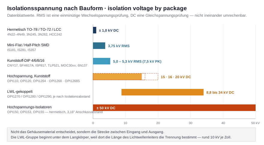
Isolation voltage in this category spans 1 kV to 50 kV, and it depends almost entirely on how far apart input and output sit inside the package. An optocoupler – also called an optoisolator or photocoupler – separates the two sides across an optical path; the package decides how long that path is. Two test procedures lie behind the figures: RMS denotes a one-minute AC withstand test, DC a direct-voltage test – the two cannot be converted into one another.
- Metal and ceramic packages (TO-78, TO-72, ceramic SMD)
Example: ±1.0 kV DC for 4N22 to 4N49, 3N245, 3N262, HCC242 - Mini-flat and half-pitch plastic packages
Example: 3.75 kV RMS for IS181, IS281, IS357 - Plastic DIP with 4 to 16 pins
Example: 5.0 to 5.3 kV RMS (7.5 kV peak) for CNY17, SFH617A, ISP817, TLP521, the MOC series, 6N137 - Elongated plastic body
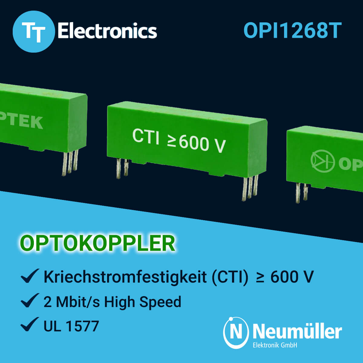
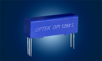
Example: ±15 kV DC for OPI110 and OPI1264, 16 kV DC for the OPI1268 with a 24.64 mm creepage path, 20 kV DC for the OPI1268S - Two separate housings coupled by optical fibre
Example: 8.8 to 34 kV DC for OPI1270, OPI1280 and OPI1290. The range starts below that of the elongated body because here the separation is set not by the package but by the chosen length of the optical fibre – roughly 10 kV per inch - Elongated body with 3.16 inch lead spacing
Example: ±50 kV DC for OPI150, OPI153, OPI155
Note: you will occasionally read that devices above about 5 kV are called optoisolators rather than optocouplers. Manufacturers do not follow that convention – TT Electronics titles both the 1 kV 4N22 and the 50 kV OPI150 "Optically Coupled Isolator".
02
Why can the CTR figures of two optocouplers not be compared directly?
A CTR figure is only ever valid together with the LED current at which it was measured – and that current differs from series to series. The current transfer ratio (CTR) is the quotient of output and input current; it falls sharply as the LED current drops, which is why identical class numbers mean different things:
- SFH617A-3 and CNY17-3: 100–200 % at IF = 10 mA, VCE = 5 V
- SFH618A-3: also 100–200 %, but already at IF = 1 mA, VCE = 0.5 V
- ISP817B and IS281B: 130–400 % and 130–260 % respectively at IF = 5 mA
- CNY75B: 30 % minimum – measured at just 1 mA
- 4N24: 40 % minimum at 10 mA; the SMD variant 4N24U quotes 100 % at the same 10 mA
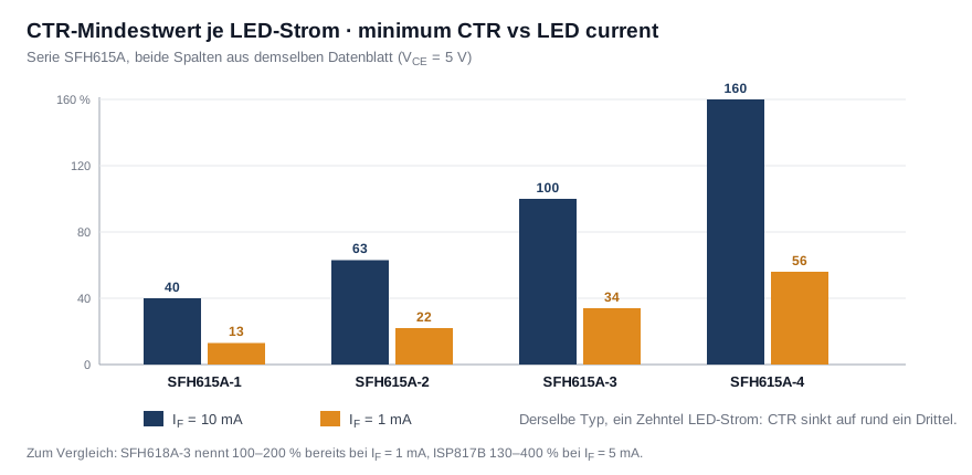
How large the effect of the test current is can be read, for example, in the datasheet of the SFH615A series, which carries two columns for the same quantity: class -3 delivers at least 100 % at 10 mA but only 34 % at 1 mA; for class -1 it is 40 % against 13 %. The minimum therefore falls to roughly a third when the LED current drops by a factor of ten.
So never compare the percentage on its own, always the pair of CTR and test current – and design for the current your circuit actually supplies, not the one in the datasheet table. If you are replacing an existing type, we will convert the figures of the candidate series to a common test current for you.
03
Why does an optocoupler fail after years even though it was never overloaded?
The most common cause is not a defect in the narrow sense but a current transfer ratio that has drifted away: the infrared LED at the input loses radiant power over operating hours, the CTR falls, and at some point the output current no longer drives the following stage reliably. From the outside this looks like a sudden failure, although no rating was ever exceeded – and a replacement part works perfectly at first.
Three countermeasures follow from the datasheets:
- Choose a class with margin. A design that barely uses up the minimum CTR has no ageing reserve from day one.
- Calculate at the actual LED current, not at the test current in the datasheet table – the difference can be a factor of three.
- Lower the junction temperature. 125 °C is the limit for the series listed here; every degree below it extends the life of the LED.
None of the datasheets in this category quotes an ageing rate – CTR is stated there only in the as-new condition and at 25 °C. We will ask Isocom Components and OPTEK Technology (TT Electronics) for the degradation data on your series before you fix the margin.
04
Which output type suits which signal?
The output type decides which signal an optocoupler can carry at all – not the isolation voltage and not the CTR. The range offers eight designs with clearly divided jobs:
- Phototransistor: slow to moderately fast digital signals and DC. Switching times of a few microseconds, strongly dependent on the load resistor. By far the largest group in the category
Example: CNY17, SFH617A, ISP817, TLP521, 4N24 - Photodarlington: very small LED currents. A CTR of several hundred to several thousand per cent, but the slowest edge in the range
Example: IS660, IS7000, ISP815, OPI123 - Logic gate: fast data lines such as SPI, UART or CAN. Defined logic levels up to 10 Mbit/s, in exchange for its own supply and a bypass capacitor close to the device
Example: 6N137, ICPL2601 - Schmitt trigger: noisy or slowly rising edges. The built-in hysteresis between turn-on and turn-off threshold turns them into a clean edge
Example: H11L1 - Phototriac: mains AC. The phototriac does not switch the load itself but fires an external power triac
Example: the MOC series, IS3021, IS6010 - Logic output in a high-voltage package: totem-pole or open-collector levels at 15 to 50 kV isolation
Example: OPI125 to OPI128, OPI155 - Photo-FET: small analogue AC and DC signals. A light-controlled, galvanically isolated resistance from below 100 Ω to above 300 MΩ, low in distortion and conducting in both directions
Example: H11F1 - Gate driver: the gate of an IGBT or power MOSFET directly, with no driver stage in between. Instead of a transistor, a complete output stage sits in the package – peak currents in the ampere range and a high common-mode rejection, so that the steep switching edge of the power device does not toggle the coupler itself
Example: ICPL3120
Equally important are the designs this category does not carry:
- Linear optocoupler with a feedback photodiode: transmits an analogue voltage under servo control, with a second photodiode correcting the LED. The photo-FET, by contrast, sets a resistance – it does not transmit a voltage.
- Capacitive and inductive isolators: above roughly 10 Mbit/s optical coupling reaches its limit. Beyond it, isolators couple through an electric or magnetic field instead of light.
- Photo-MOSFET: switches the load itself at a low on-resistance and is therefore no longer an optocoupler but a solid-state relay. Manufacturers accordingly list these types as a separate group, "Solid State Relays".
05
What is the phototransistor base terminal for – and why do some series leave it out?
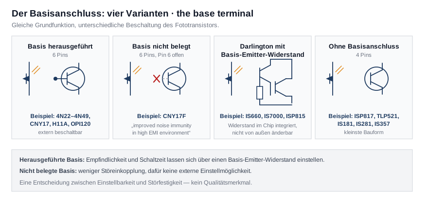
The base terminal makes the phototransistor externally biasable: a resistor from base to emitter drains the dark current, lowers sensitivity and shortens the fall time. But that same pin is also an aerial: an open, high-impedance base picks up interference and makes the output sensitive to steep voltage edges.
The resulting rule is simple: if you are not going to fit a base resistor, do not bring the base out at all – an open pin offers nothing but drawbacks in this configuration. Conversely, the base terminal is the only way to shift the sensitivity and switching time of a finished optocoupler without changing series.
06
How do you tell whether a triac optocoupler is usable for phase-angle control?
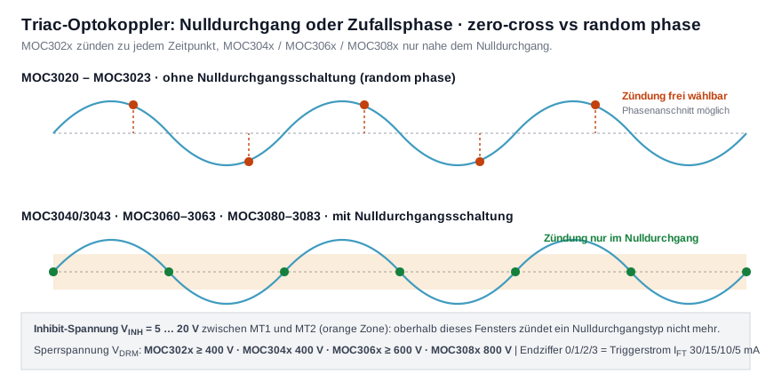
By the zero-crossing circuit in the output – and that is stated not in the order number but in the first line of the datasheet. Types with a zero-crossing circuit will not fire at all above an inhibit voltage of 5 to 20 V between MT1 and MT2. That is precisely their purpose: they switch the load at the voltage zero crossing to keep inrush current and emitted interference low. This makes them unusable for phase-angle control – the most common reason a dimmer built around an MOC3063 fails to work.
Across the range this divides as follows:
- Without zero crossing ("random phase"): MOC3020 to MOC3023, MOC3052, IS3021, IS3052, IS6010 – freely chosen firing instant, VDRM at least 400 V, dv/dt at least 1,000 V/µs
- With zero crossing: MOC3040–3043 at 400 V, MOC3060–3063 at a minimum of 600 V, MOC3080–3083 at 800 V blocking voltage
The final digit means the same in all four MOC families – the trigger current IFT: 0 = 30 mA, 1 = 15 mA, 2 = 10 mA, 3 = 5 mA. An MOC3023 and an MOC3063 therefore need the same LED current and still behave in completely different ways. On blocking voltage, margin pays: on a 230 V mains supply the peak value alone is around 325 V, so 400 V leaves little headroom for switching transients.
07
Can an optocoupler transmit an AC signal?
Yes – but not with every type. At the input of an optocoupler sits a light emitting diode, and a diode conducts in one direction only. The negative half-cycle appears across it as reverse voltage, and ordinary series withstand only a few volts of it – often 6 V, and on the hermetic types just 2 V. Anything beyond that destroys the LED, even if the series resistor limits the forward current correctly. An ordinary optocoupler fails on AC not because the signal is too large, but because its polarity is wrong.
Three routes lead to the goal:
- An optocoupler with an AC input. Two antiparallel light emitting diodes in the package: each half-cycle finds its own LED and polarity no longer matters
Example: ISP620, SFH620A, IS280-4 - A protection diode antiparallel to the LED on an ordinary type. It absorbs the reverse voltage but passes only the positive half-cycle – enough for simple presence detection.
- A photo-FET, where the signal is not merely to be detected but carried with low distortion. It is the only output in this category that is bidirectional and conducts in both directions
Example: H11F1
Three points apply in every case. The output follows every half-cycle: the phototransistor produces a pulsating signal at twice the mains frequency, which the evaluating circuit must smooth or count. The series resistor must handle the full half-cycle, not the RMS value – and sustain the resulting power dissipation continuously. And the isolation voltage must suit the application, not the signal: with mains voltage at the input it decides the protective separation. If the aim is to switch mains AC rather than sense it, the phototriac types are the right choice.
08
Why use an optocoupler instead of a relay – and when does a relay remain the better choice?
An optocoupler replaces a relay wherever a signal has to be isolated – not where power is switched. The difference can be read off the output currents: the phototransistor types in this category are limited to 50 mA collector current, the darlington types to 80 to 150 mA, the phototriacs to 100 mA RMS on-state current. A small relay switches amperes.
Where the optocoupler wins:
- Speed: for example 10 Mbit/s for the 6N137 against milliseconds for a relay
- No mechanical wear: no contact bounce, no arcing, no limited number of operations
- Control power: 1 to 10 mA of LED current suffices, where a relay needs coil power and often a driver
- Size and noise: a DIP-4 instead of a relay body, and silent
Where the relay stays: at load currents in the ampere range, where a genuinely volt-free contact without leakage is required – an optocoupler output never blocks completely – and in applications that need an unchanged switching point over years, because CTR drifts as the LED ages. The usual compromise is both together: the optocoupler isolates the signal, a triac or transistor behind it switches the load. That is exactly what the phototriac types are built for.
09
How much power may an optocoupler still dissipate at 70 °C?
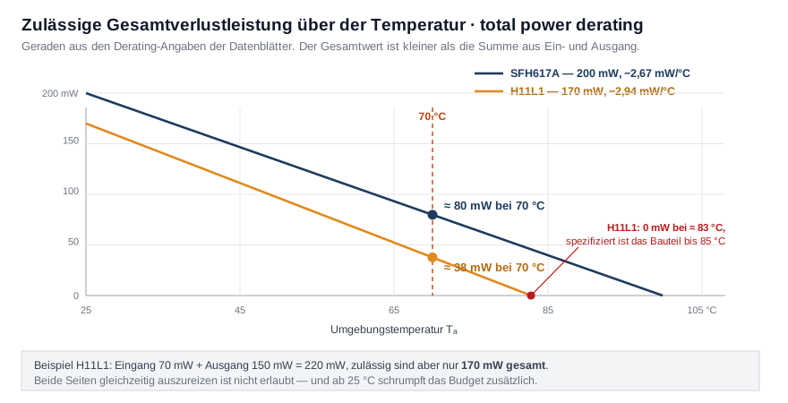
At 70 °C an optocoupler may dissipate considerably less than at 25 °C – and less than the sum of the individual figures suggests. An optocoupler holds two dies in one package, so the datasheets quote three limits: one for the input LED, one for the output and one for the device as a whole. The third is smaller than the sum of the first two – the H11L1, for example, lists 70 mW and 150 mW against 170 mW in total, while IS281, ISP321 and TLP321 give 70 + 150 mW against 200 mW. Running both sides at their limit simultaneously is therefore ruled out.
Temperature is then governed by the derating line:
- SFH617A: 200 mW from 25 °C, −2.67 mW/°C → about 80 mW at 70 °C
- H11L1: 170 mW from 25 °C, −2.94 mW/°C → about 38 mW at 70 °C
For the H11L1 the end of that line is worth a look: 170 mW ÷ 2.94 mW/°C gives 57.8 °C of headroom, so it reaches zero at roughly 83 °C – although the device is specified to 85 °C. Over the last two degrees no power dissipation is arithmetically permissible at all. For the SFH617A, by contrast, derating line and temperature limit agree cleanly: zero at 100 °C, exactly at the end of the operating range. The operating temperature on its own therefore says nothing about what the device may still deliver there.
10
Can optocouplers be customised?
Yes – in parameters the datasheets themselves mark as selectable. Isocom Components notes "Custom electrical selections available" or "Special Selections are available on request" for most series, while OPTEK Technology (TT Electronics) lists the options as separate order numbers:
- CTR class: more tightly selected bins instead of the standard classes
- Lead spacing: standard DIP or a wider spread for more creepage – for example 10.16 mm for a creepage distance of at least 8.0 mm
- Mounting: through-hole, surface mount or tape and reel
- Approval variant: for example a VDE-approved version
- Screening level: standard, TX or TXV, and JAN, JANTX and JANTXV to MIL-PRF-19500
- Isolation distance on the fibre-coupled isolators: 18, 26, 32, 66 or 80 mm. The digits in the order number are precisely that distance in millimetres, at more than 10 kV per inch.
Tell us the target values of your application – isolation voltage, LED current, required output current, ambient temperature and package – and we will clarify with Isocom and TT Electronics which combination can be built.
Services
We support you in every phase of your project. From the initial idea to series production, we accompany you with expertise, state-of-the-art technology, and customized solutions.

Why customers rely on us
For decades, we have been supporting our customers with tailor-made solutions, technical expertise, and personal service. This trust forms the basis for successful, long-term partnerships.
Customized solutions
Whether standard or custom solutions -
we deliver exactly what you need.
All in One
Distribution, development, production -
comprehensive service from a single source.
Innovative Technologies
Future technologies in use
for modern solutions with vision.
Personal project support
Reliable support right from the start -
on site, via call, or by phone.
Years of experience
Successful on the market since 1952
with in-depth industry expertise.
Network
Manufacturer expertise directly available
for development, innovation & optimization
Integration Level
High system integration with a concept
for efficiency and reduced complexity.
Technical expertise
Know-how and experience combined
for sustainable electronics solutions.
Sustainable
Responsible and resource-conscious
selection of components and supply chains.
Framework agreements
Predictable prices and supply -
tailored to your individual needs.
9001:2015
Certified processes for maximum
safety, quality, and compliance.
Logistics solutions
Kanban, consignment, min-max, and more
for availability and less inventory.
Customers who
trust us.
Latest News on Optocouplers
Stay up to date with the latest product news, technical innovations, and trends in the field of Optocouplers.


